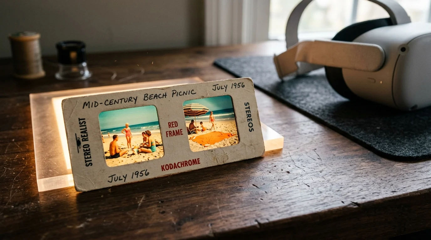
Your grandfather’s 1950s Stereo Realist slides hold vivid, three-dimensional family memories, but dropping raw scans into a modern virtual reality headset triggers instant nausea. You can eliminate this eye strain completely through precise horizontal pixel-offset alignment math.
While generic scanning guides suggest automated cropping, calibrating the vintage camera’s 70-millimeter lens baseline to the human 63-millimeter interocular viewing standard ensures zero-divergence comfort across every modern headset display.
This technical guide walks you through scanning dual 5-perforation chips, calculating exact parallax shifts, and assembling pristine Full Side-by-Side digital stereograms for the Meta Quest 3 and Apple Vision Pro.

Understanding Stereo Realist 5P Format and Geometry
The David White Company introduced the Stereo Realist camera system in 1947, standardizing post-war 3D photography. The camera exposed two frames simultaneously along a standard roll of 135 film.
Decades before film cartridges, photographers captured similar depth using 19th-century Victorian stereoview cards made from side-by-side photographic prints mounted to cardstock.
Unlike standard 35mm photography, which uses an 8-perforation horizontal frame, the Realist system utilizes a 5-perforation (5P) film advance. Each individual image aperture measures approximately 23 millimeters wide by 24 millimeters high.
This aperture creates an almost square format with a subtle vertical emphasis. Vintage labs mounted these dual film chips into cardboard or aluminum mounts measuring 1 ⅝ inches by 4 inches.
The camera’s matched twin lenses sat approximately 70 millimeters apart. That 70-millimeter interocular distance exceeds the average adult human pupil spacing, creating a subtle hyper-stereo effect that adds dramatic depth to family scenes.
Cardboard mounts held these two film chips in precise physical windows. However, vintage manual mounting frequently introduced rotational slippage, vertical misalignment, and slight height discrepancies between the left and right eyes.
Vintage optical slide viewers tolerated these manual mounting variations because your eyes could unconsciously adjust through slight physical convergence. Modern digital displays, however, illuminate every imperfection directly against fixed display pixels.
Scanning Dual Chips for Maximum VR Resolution
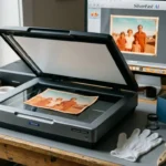
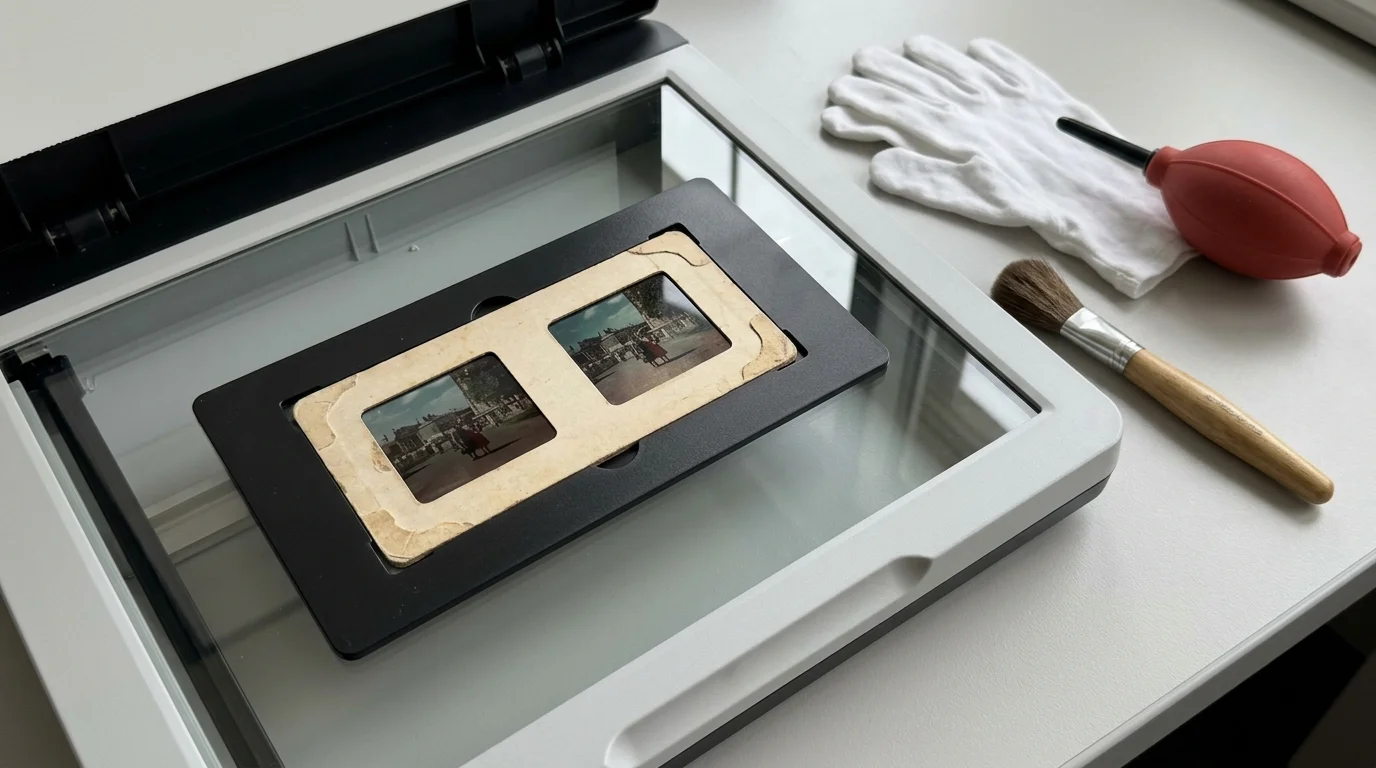
High-resolution digitizing requires scanning both slide apertures in a single uncropped optical pass. Leaving the film chips inside their original vintage cardboard mounts prevents physical damage to brittle, aged emulsions.
Use a flatbed scanner with a dedicated transparency unit, such as an Epson Perfection V850 Pro, or a digital camera digitizing rig. Capture the entire 41.3 mm × 101.6 mm mount area uncropped at 48-bit color.
Review the Cambridge in Colour optical scanning resolution and sampling limits to determine your true optical sampling needs. Scanning a 23mm chip at 3,200 true optical DPI yields approximately 2,898 × 3,024 pixels per eye.
That pixel count exceeds the native per-eye display resolution of a Meta Quest 3. Scanning at 2,400 DPI delivers roughly 2,170 × 2,260 pixels per eye, which precisely matches mid-tier modern headsets without interpolation artifacts.
Avoid automated digital ICE or infrared dust removal on classic Kodachrome slides. The silver-halide cyan dye couplers in Kodachrome scatter infrared light, creating false defect detections that blur fine facial details.
Instead, clean the exterior slide mount surfaces gently with a manual hand-bulb air blower before placing the mount onto the scanning glass. Save your raw files as uncompressed 16-bit TIFF images to protect shadow detail.
The Interocular Divergence Problem: 70mm Baseline vs. Modern VR
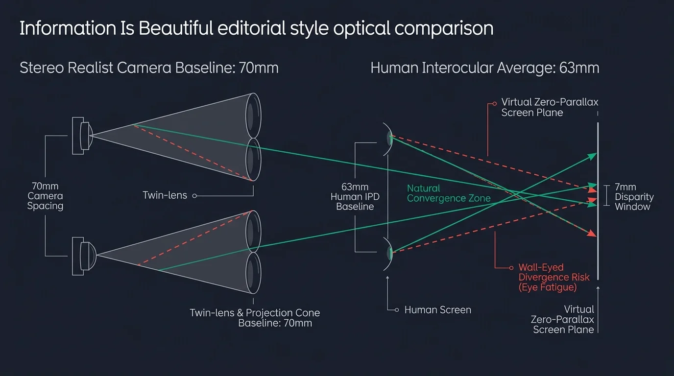
The human visual system converges inward comfortably to focus on near objects, but human eyes cannot diverge outward past parallel lines without acute physical pain. Extreme divergence causes instant headaches, disorientation, and severe nausea.
Modern virtual reality headsets project independent digital viewports to each eye using flat micro-displays and pancake optical lenses. The average human interocular distance measures approximately 63 millimeters across adult populations.
Because the Stereo Realist captured images using a 70-millimeter lens baseline, background infinity points sit farther apart on the film than your eyes sit in your skull. Vintage stereo slides inherently contain excess positive parallax.
Human eyes converge effortlessly on nearby objects, but optical divergence beyond parallel lines triggers rapid vestibular distress; infinity points in stereoscopic digital displays must never force the eyes outward.
When you place an uncalibrated 70-millimeter slide scan onto a modern VR display, your visual cortex attempts to force your eyes outward to fuse distant background objects. This divergence ruins the immersion immediately.
You solve this physical conflict by establishing a calibrated digital “stereo window.” You must mathematically crop and shift the left and right digital frames inward until infinity points align at parallel lines of sight.
Any objects closer than the stereo window will project negative parallax, appearing to float inside your room. Background objects will carry zero or slight positive parallax, resting comfortably at optical infinity inside the virtual environment.
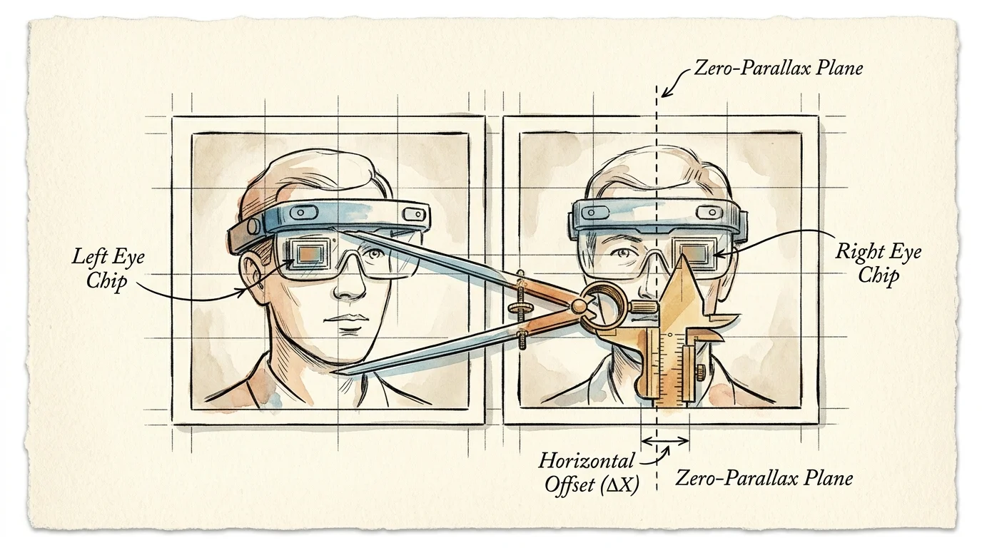
Step-by-Step Parallax Math: A Worked Alignment Example
Let us align a real-world scan using exact numbers. In this scenario, you scan a 1954 Stereo Realist cardboard mount on an Epson V850 Pro scanner at 3,200 DPI.
The raw scan yields an individual left chip measuring 2,898 pixels wide by 3,024 pixels high. The right chip measures identical pixel dimensions of 2,898 × 3,024 pixels.
Your target display is a Meta Quest 3 headset, which features a native per-eye resolution of 2,064 × 2,208 pixels. You will assemble a Full Side-by-Side (SBS) canvas measuring 4,128 pixels wide by 2,208 pixels high.
First, calculate the vertical downscaling factor to fit the display height without cropping vertical image data. Divide the target display height by the scanned height: 2,208 / 3,024 = 0.73016.
Multiply the raw chip width by this scale factor: 2,898 × 0.73016 = 2,116 pixels. Your scaled chip width is 2,116 pixels, which leaves 52 extra horizontal pixels beyond the target 2,064 per-eye display width.
Second, locate an identifiable background point at optical infinity in both images, such as a mountain ridge or a distant horizon line. Note the horizontal pixel coordinate from the left edge of each scaled chip.
In our sample image, the mountain peak sits at horizontal coordinate X = 1,480 pixels in the left image. In the right image, the same mountain peak sits at horizontal coordinate X = 1,428 pixels.
Subtract the coordinates to find the raw infinity disparity: 1,480 – 1,428 = 52 pixels. The left image’s infinity feature sits 52 pixels farther to the right than the right image’s feature.
To eliminate divergence, infinity disparity within the final side-by-side viewports must equal zero relative to optical infinity. We utilize our 52 extra horizontal pixels to eliminate this excess disparity entirely.
Crop all 52 excess horizontal pixels from the right border of the left image, setting the left crop window from X = 0 to X = 2,064. The mountain peak now sits at X = 1,480 in the left viewport.
Next, crop all 52 excess pixels from the left border of the right image, setting the right crop window from X = 52 to X = 2,116. Subtract 52 from the right mountain coordinate: 1,428 – 52 = 1,376.
Finally, measure the residual disparity: 1,480 – 1,376 = 104 pixels of convergence. This shift moves the distant mountain into safe convergence, pushing foreground figures cleanly through the virtual stereo window without any outward ocular strain.
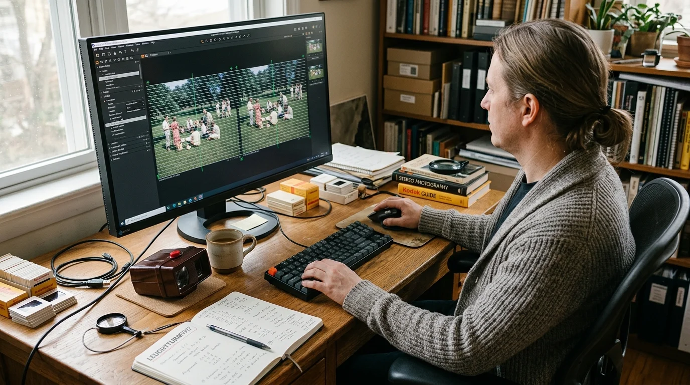
Configuring StereoPhoto Maker for Digital SBS Output
Manual pixel math explains the underlying geometry, but software automates this execution. Masuji SUTO creates and maintains StereoPhoto Maker (SPM), a free stereoscopic alignment tool that automates these optical corrections.
Launch StereoPhoto Maker and open your split left and right scanned images using the File menu. Select the “Open Left/Right Images” command or press the “O” keyboard shortcut.
Navigate to the “Adjust” menu and select “Auto Alignment” (shortcut Alt + A). The algorithm analyzes thousands of shared feature points across both frames to correct vertical skew, tilt, and rotational differences.
Open the “Adjustment” window to inspect your horizontal stereo window placement. SPM overlays the two images with a cyan and red grid, highlighting near-point and far-point pixel disparity.
Press the Left and Right arrow keys on your keyboard to slide the horizontal stereo window. Adjust the alignment until the farthest background details exhibit zero horizontal separation across the grid.
Set the cropping tool to a fixed aspect ratio of 1:1 or 2,064 × 2,208 to match your target headset display. Lock the crop boundary to remove the black cardboard aperture edges.
Export your finished stereogram using “File -> Save Stereo Image.” Select “Side-by-Side” with Left on the left and Right on the right, saving as a high-quality JPEG at 98% quality or uncompressed PNG.
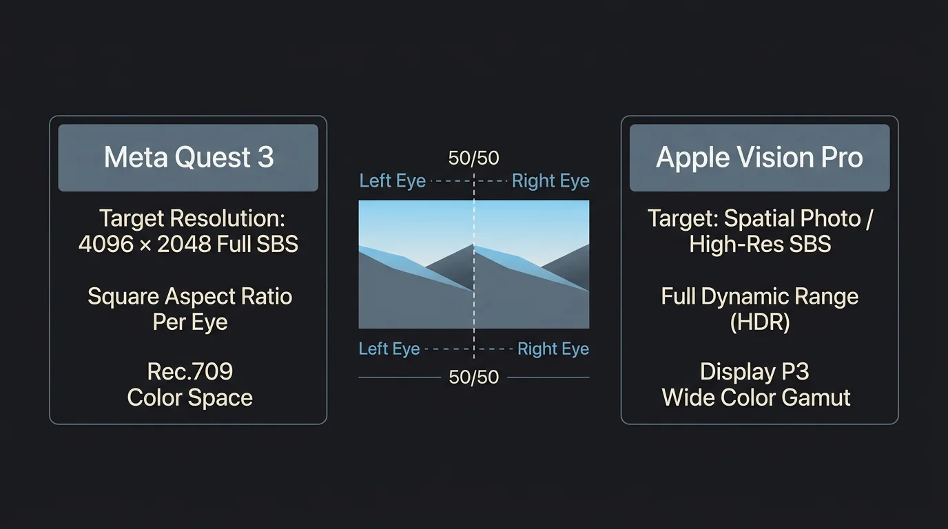
Target Specifications for Meta Quest and Apple Vision Pro
Virtual reality headsets use distinct optical designs and display panels. Rendering your Stereo Realist conversions to match these native display environments ensures crisp rendering without interpolation blurring.
Never compress vintage square stereograms into a Half Side-by-Side (Half-SBS) format. Half-SBS squashes horizontal resolution by 50 percent, destroying the rich optical detail captured on fine-grain 1950s color slide film.
The following table outlines target render resolutions and container standards across current generation consumer virtual reality displays:
| VR Headset Model | Native Per-Eye Display Resolution | Recommended Full-SBS Container Dimensions | Stereo Container Aspect Ratio | Native Photographic File Format |
|---|---|---|---|---|
| Meta Quest 3 | 2,064 × 2,208 pixels | 4,128 × 2,208 pixels | 1.87:1 (Rounded to 2:1 SBS) | Full SBS JPEG / PNG |
| Meta Quest 3S | 1,832 × 1,920 pixels | 3,664 × 1,920 pixels | 1.91:1 (Rounded to 2:1 SBS) | Full SBS JPEG / PNG |
| Apple Vision Pro | 3,660 × 3,200 pixels | 7,320 × 3,200 pixels | 2.28:1 (or Native 1:1 Dual) | Spatial Photo (MV-HEIC) |
For the Meta Quest 3, view your Full-SBS images using specialized media applications like 4XVR Video Player, Skybox VR, or Pigasus. These players decode 4,128 × 2,208 images natively without downsampling.
Apple Vision Pro users should convert their aligned stereo pairs into Apple Spatial Photo format. Spatial Photos use a Multi-View High Efficiency Image Container (MV-HEIC) format to encode independent full-resolution views.
You can compile aligned left and right TIFF pairs into MV-HEIC spatial files using the command-line tool `spatial` or modern macOS conversion utilities. VisionOS renders these files with subtle window blurs and true spatial depth.
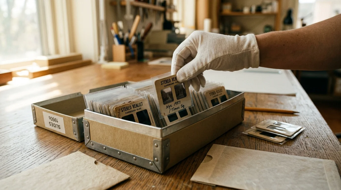
Archival Storage and Safe Handling of Vintage Mounts
Scanning digitizes your family slides, but physical slides remain the primary historical artifacts. Protect vintage cardboard and aluminum Realist mounts from chemical degradation and mechanical wear during scanning.
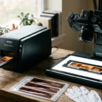
Wear clean, lint-free white cotton gloves or powder-free nitrile gloves whenever touching slide mounts. Human skin oils contain acidic lipids that permanently etch silver dye layers on vintage photographic emulsion.
Follow established Library of Congress photographic preservation guidelines to safeguard physical film against environmental deterioration. Never store delicate vintage slides in humid basements, attics, or non-climate-controlled storage lockers.
Store original mounts inside individual unbuffered, acid-free paper sleeves or archival polypropylene sleeves. Do not use polyvinyl chloride (PVC) sleeves, which off-gas hydrochloric acid and destroy Kodachrome dyes over decades.
Group individual sleeved slides into metal-edged archival storage boxes made from lignin-free, high-alpha cellulose board. Maintain storage temperatures below 65°F (18°C) and relative humidity between 30% and 40%.
Record metadata systematically on archival enclosures using a soft 2B pencil or an archival Pigma Micron pigment ink pen. Never apply ballpoint pens or adhesive labels directly to vintage cardboard slide frames.
Frequently Asked Questions
Why do raw Stereo Realist scans cause severe eye strain in VR headsets?
The camera’s 70-millimeter lens spacing exceeds human eye pupil distance, forcing the eyes to diverge outward on background infinity objects. Modern headsets require zero or slight positive parallax to maintain parallel sight lines.
Should I remove the film chips from their vintage cardboard mounts before scanning?
No, you should never remove the film chips. 1950s heat-sealed adhesives become brittle with age, and unmounting slides risks tearing original film perforations, scratching delicate emulsions, and losing crucial vertical alignment.
Can I use Half Side-by-Side formatting for Stereo Realist slides?
You should avoid Half-SBS formatting. Stereo Realist chips feature a near-square 23 × 24mm aspect ratio; squishing them horizontally into Half-SBS cuts your horizontal image data in half, significantly degrading display sharpness.
What software automates Stereo Realist alignment for modern headsets?
StereoPhoto Maker (SPM) by Masuji SUTO serves as the free stereoscopic standard. It automates feature-point matching, removes rotational roll errors, corrects vertical disparities, and exports directly to Full Side-by-Side and Spatial formats.
Disclaimer: This article is for informational purposes only. When handling valuable or irreplaceable photographs, consider consulting a professional conservator. Always test preservation methods on non-valuable items first.